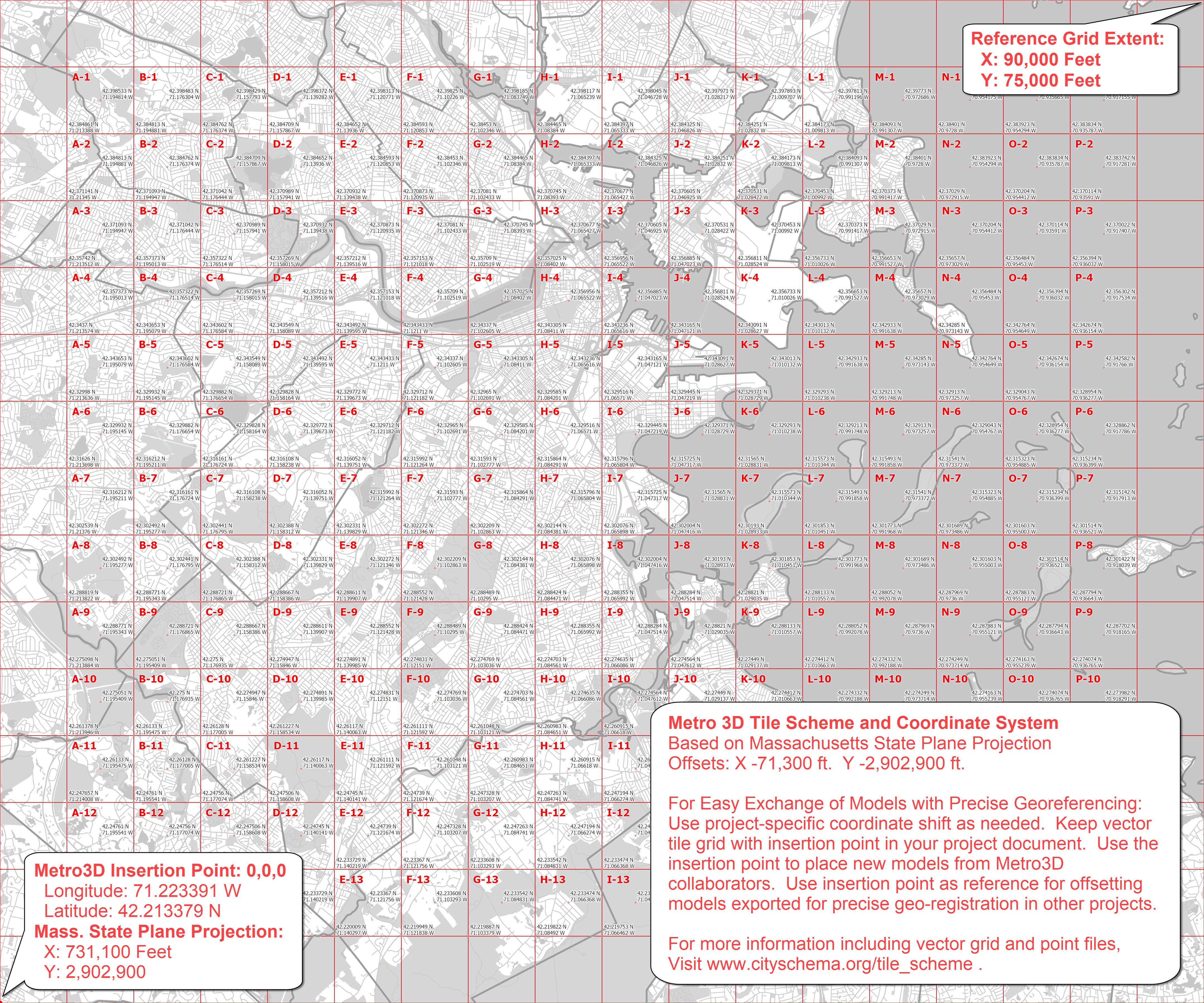
Tile Grid and Coordinate System
Click image to view full-size reference image.
File Name: BOS3D Tile Grid
Updated: July 6, 2021
Formats: Autodesk DXF, Trimble Sketchup, ESRI Shapefile, GeoJSON
Tiling Strategy
The tiling scheme for the BPDA's 3D model serves as a framework for sharing a detailed model of metropolitan extent with design tools that are limited in terms of spatial extent and file-size. By dividing the city-wide model components into snap-together modules, the tile grid provides a framework for registering model collections and terrain meshes that can be precisely snapped together and draped with a variety tiled groundplan images.
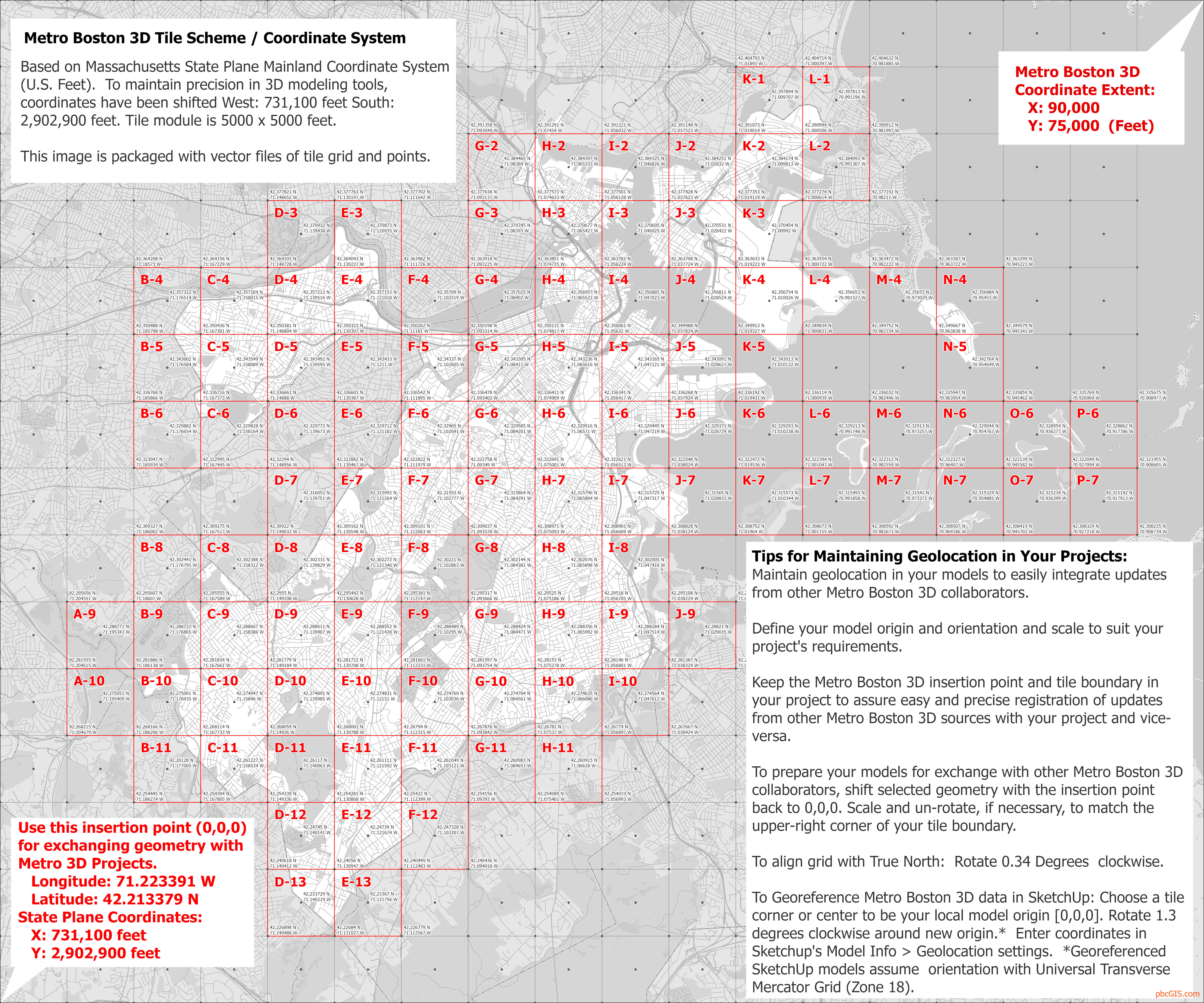
Metro Boston 3D Coordinate System
Surveyors and engineers in Massachusetts prepare their official drawings using the Massachusetts State Plane Coordinate System with coordinates expressed in Feet. The origin of the State Plane grid lies outside the state, which makes coordinate references much larger numbers than most most 3D modeling tools can deal with gracefully. The creators of AutoCAD, 3DsMax, Rhino, SketchUp and Blender all recommend moving geospatially referenced geometry closer to the origin to avoid problems of precision when creating, transforming or rendering.
To facilitate on-going exchange of 3D models, we have chosen a default offset that places the origin to the South-West of Boston and neighboring cities. We expect modelers to use project-specific coordinate origins. Preserving the Metro3D insertion point and a tile boundary with models will make it easy to incorporate updates and exchange models with other Metro 3D Boston users whith perfect geo-registration.
Projected Coordinate System: State Plane Massachusetts Mainland (Feet), North American Datum of 1983.
Vertical Coordinate System for 3D data: North American Vertical Datum, 1988 (NAVD 88) Feet (Height)
Origin / Offset / Insertion Point
The origin of the Metro 3D Boston coordinate system serves as the insertion point for models.
- State Plane Coordinates:
- X:731,100 feet
- Y:2,902,900 feet
- Geographic:
- Longitude: 71.223391 W
- Latitude: 42.213379 N
To align Metro 3D Boston grid with True North: Rotate 0.34 Degrees clockwise.
To georeference SketchUp tiles for interoperability with SketchUp's geolcoation tools, see the Notes at the bottom of the SketchUp Models page.
Tips for Geo-Location and Integrating Updates
Maintain geolocation in your models to easily integrate updates from other Metro Boston 3D collaborators.
- When importing this reference grid into your model be sure to specify units of Feet and check the tile-width (5000 feet) to be sure.
- Define your model origin, orientation, and scale to suit your project's requirements.
- Keep the Metro 3D insertion point and tile boundary in your project to assure easy and precise registration of updates from other Metro Boston 3D sources with your project and vice-versa.
- To import new models from Metro 3D Boston users, snap to the original insertion point. It may no longer be at 0,0,0, but it is the relative location that counts.
- To prepare your models for exchange with other Metro Boston 3D collaborators:
- shift selected geometry with the insertion point back to 0,0,0. Scale and un-rotate, if necessary, to align the upper-right corner of your tile boundary with the reference grid.
- Now you can export or import geometry for easy snap-in registration!
Download City-Wide Tile Grid Resources
- ArcGIS Projection file for Metro 3D Boston coordinate system.
- Tile reference image in .OBJ format or JPEG.
- Tile Polygons and Points (including insertion-point and bounding rectangle)
- SketchUp format.
- DXF format Metro Boston 3D coordinate system or Un-shifted State Plane Feet -- useful for registering data layers from unshifted State-Plane data-sets.
- Shapefile format. useful for clipping ground plan images or vector data to precisely register with tiled models.
- GeoJSON format. Helpful for automating processes that involve coordinate transformation of tiled models (see Data Dictionary, below.
Data Dictionary for Tile Grid Attribute Table
This attribute table is a reference for tile identifiers and tile-center coordinates.
Since the tiles are 5000 feet and square with the State Plane grid, eht state-plane coordinates fom the corners can be calculated by adding or subtracting 2500 feet frm the center coordinate.
| Field Name | Type | Description |
|---|---|---|
Town_Code |
Text |
A three letter abbreviation of the town name. |
Tile_Label |
Text |
a hyphenated label consisting of the letter designating the tile column and the number reflecting the tile row. |
Tile_ID |
Text |
A concatenation of the Town_Code, underscore, and the Tile_Label string. This identifier is used for naming tiled models and folders elminates tile name conflicts for modeling projects that span multiple towns. |
Center_Lat |
Text |
The latitude of the center of the tile. Assuming the WGS84 earth model. |
Center_Lon |
Text |
The longitude of the center of the tile. Assuming the WGS84 earth model. |
BosShift_X |
Text |
The X coordinate of the tile center. Metro Boston 3D coordinate system |
BosShift_Y |
Text |
The Y coordinate of the tile center. Metro Boston 3D coordinate system |
MASP_X |
Text |
The X coordinate of the tile center. Massachusetts State Plane (Mainland, Feet) coordinate system |
MASP_Y |
Text |
The Y coordinate of the tile center. Massachusetts State Plane (Mainland, Feet) coordinate system |